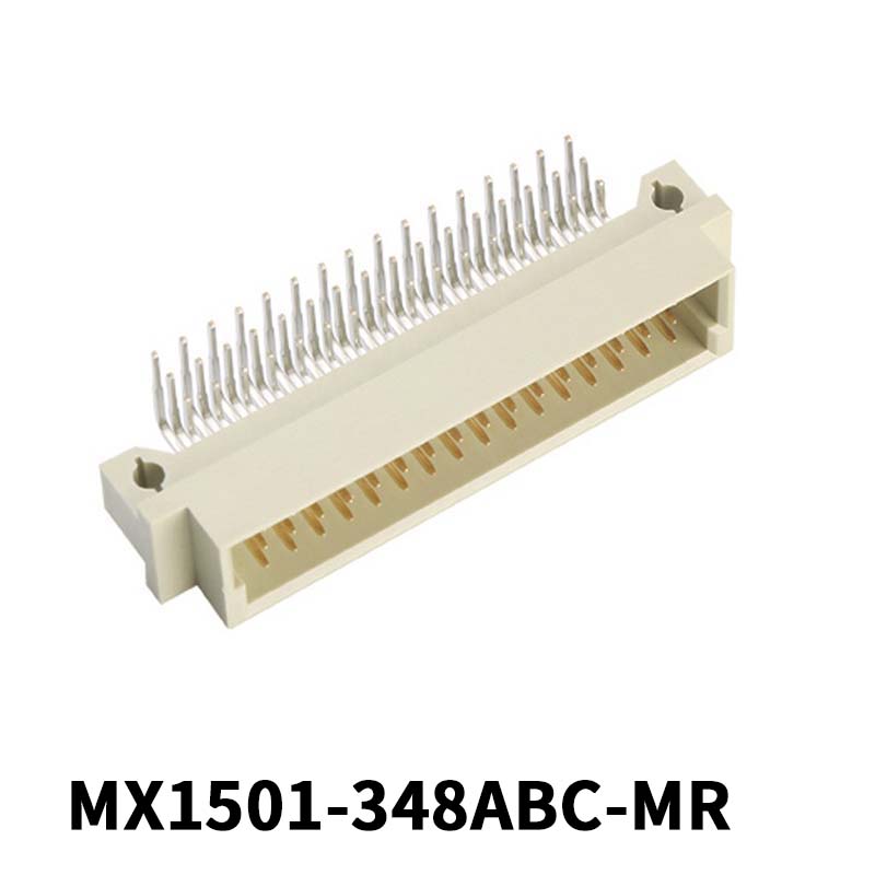
DIN41612 connector is a type of connector that adopts European standards and is widely used. It is usually used in 19in standard chassis. In its installation process, positioning accuracy, installation firmness, and replaceability are crucial. Positioning accuracy can ensure that the connector is accurately docked when the circuit board is loaded into the chassis; the installation firmness is used to ensure that the connector does not fall off or shift when the circuit board is unplugged, to ensure the repeatability of plugging and plugging; replaceability is used for When the upper part of the connector of the same chassis needs to be disassembled or replaced, it can be operated conveniently and quickly.
There are generally two installation methods for DIN41612 European connectors:
1. Make the flat connector of the same chassis into a connector backplane, and then fix it on the chassis. The mode of the backplane can make the interconnection between the entire row of connectors simple and stable, and the connections are all in Wires are routed in the PCB, and the installation of the backplane is also very convenient. When a connector in the backplane needs to be removed, the entire backplane needs to be disassembled, and the backplane needs to be returned to the PCBA manufacturer to repair the connector, which is very inconvenient and the cycle will also be Very long, so the replacement cost of the backplane mode connector will be relatively large.
2. Install the flat connector of the same chassis on the connector fixing strip, and then install the connector fixing strip on the chassis, or install the fixing strip on the chassis first, and then install the connectors one by one from the inside of the chassis Install on the fixing bar. This mode of connector installation is not very convenient, and it is not easy to determine the left and right installation positions of the connector. When a connector fails and needs to be removed, it is necessary to remove all the circuit boards on the front of the chassis, and then remove it from the chassis. Internal disassembly, the operation process is relatively cumbersome; using this installation method, there will be cables connected to the end of the connector, if a shielded cable is used, the shielding layer grounding problem of the shielded cable will be extremely difficult to solve.
 简体中文
简体中文 English
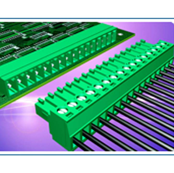
 English